




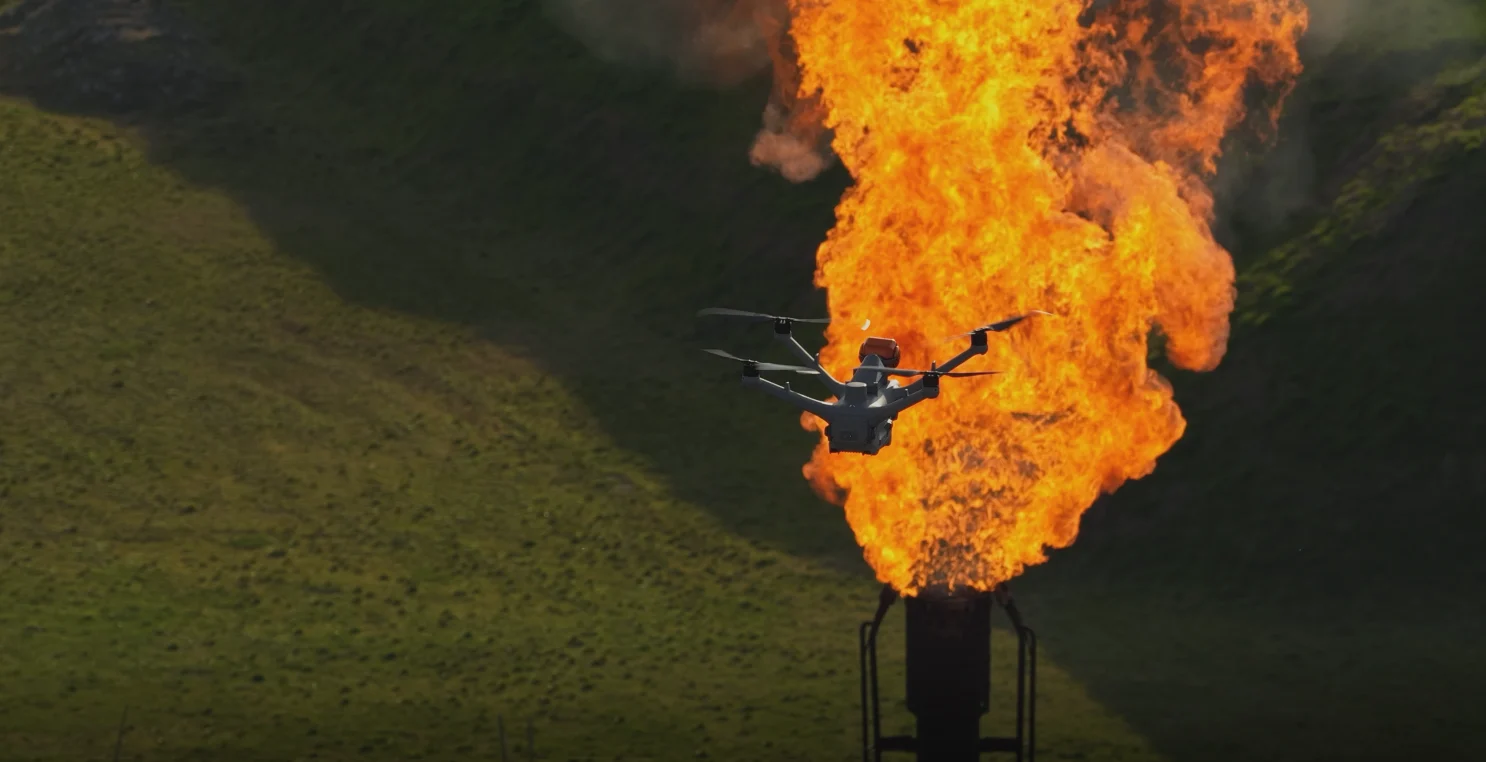

Storage tanks can release vapors even when no product is being transferred. Changes in temperature, pressure and liquid level all affect vapor movement. Understanding these mechanisms helps inspection teams select observation points and interpret what they find.
This guide focuses on atmospheric fixed-roof and floating-roof tanks storing volatile organic liquids.
1. Breathing and working losses
A fixed-roof tank normally has a vapor space above the liquid.
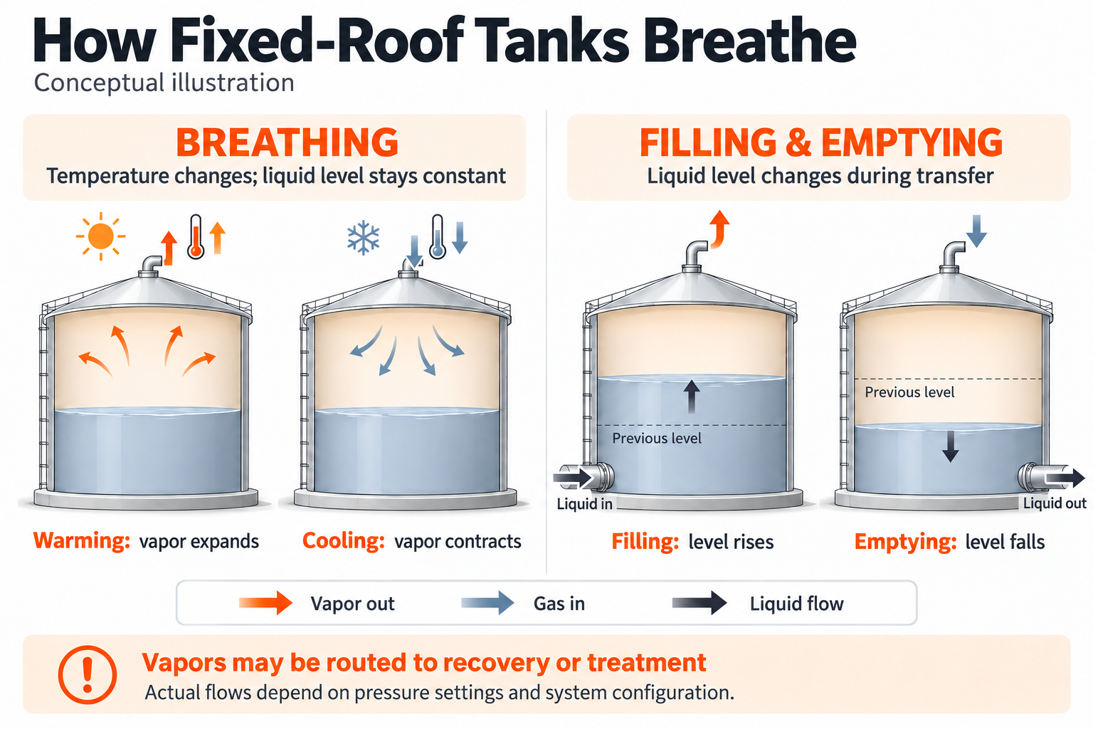
Breathing, or standing losses, can occur without a change in liquid level. Temperature and atmospheric pressure changes affect the vapor space. Warming can cause vapor expansion and outbreathing; cooling can cause contraction and inbreathing, depending on the vent settings and system design.[1][2]
Working losses are associated with product transfer. During filling, the rising liquid level reduces the vapor space and can displace vapors. During emptying, gas may need to enter to maintain the pressure balance.[1][2]
Vapor displacement and release to the atmosphere are separate stages. Displaced vapors may be routed to a collection, recovery or treatment system. Their final destination depends on the installation and its operating condition.
2. Floating-roof tank emissions
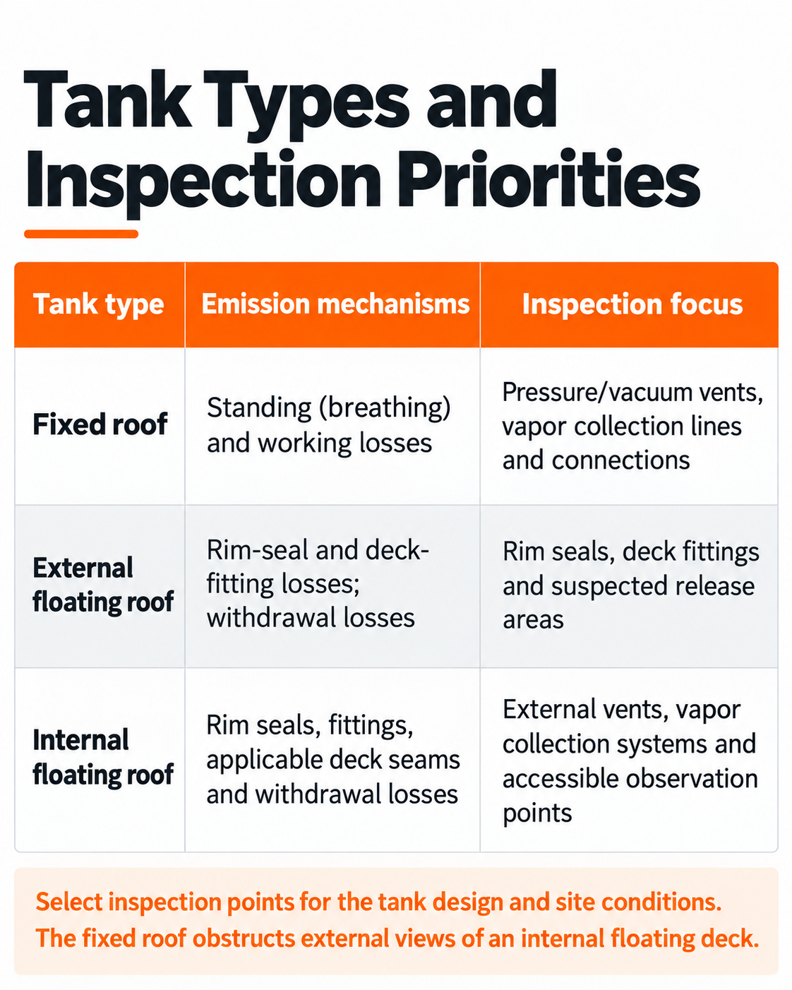
Floating roofs move with the liquid level to reduce evaporative losses. Inspection priorities include rim seals, deck fittings and deck seams where applicable. During withdrawal, liquid remaining on exposed tank walls can also evaporate.[1][3]
Tank types and inspection priorities
3. Interpreting a gas plume
A plume in optical gas imaging (OGI) footage provides a location and dispersion cue. To investigate the cause, check:
- Was the tank filling, emptying or changing operating state?
- Did the plume appear at a designed vent or near a seal or fitting?
- What was the status of the vapor collection or treatment system?
- Did the observation persist or recur under comparable conditions?
A short video alone does not establish the gas composition, a specific equipment fault or compliance status. Plume imagery should be assessed alongside operating records and site verification.
The stored product and process determine which gases may be present. Confirm that the target gas is within the camera's response range before selecting OGI for the task.
4. Recording inspection findings
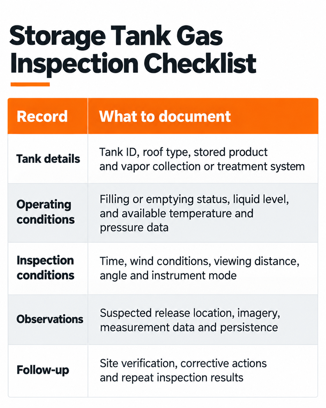
Record the conditions alongside the imagery so that findings can be checked and compared later.
Storage tank gas inspection checklist
5. OGI and methane remote sensing in practice
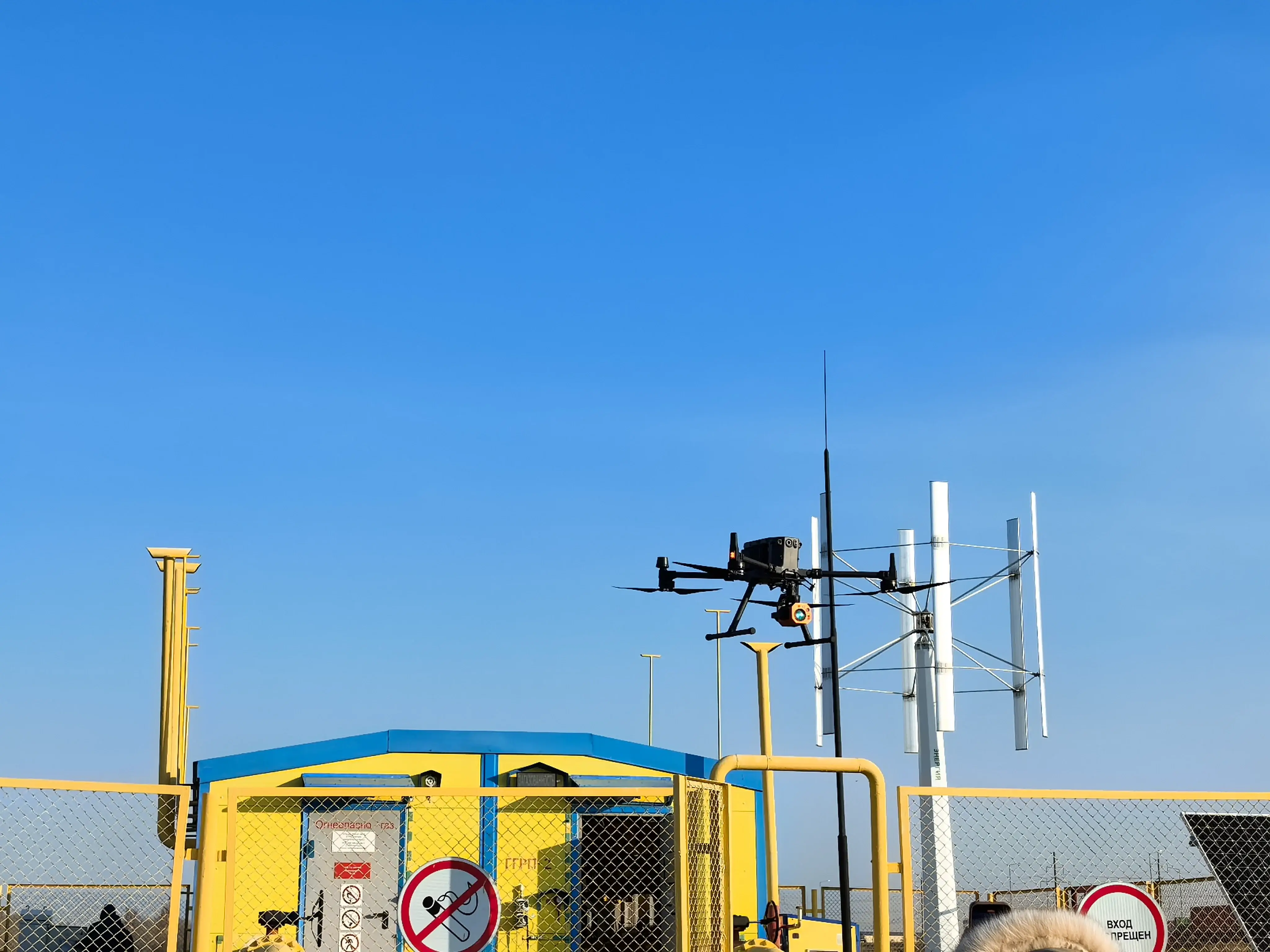
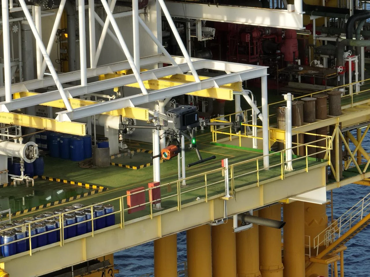
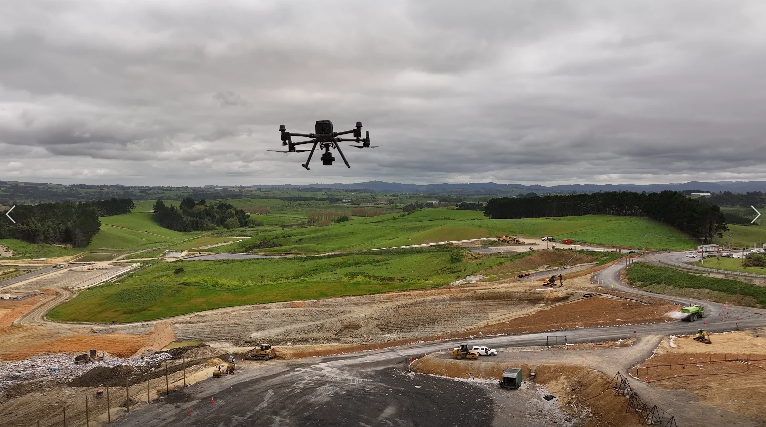
The BLV GasVision-TD1 combines OGI with TDLAS methane remote sensing. Its OGI channel visualizes gases within its response range, while the TDLAS channel measures methane path-integrated concentration in ppm·m.[4]
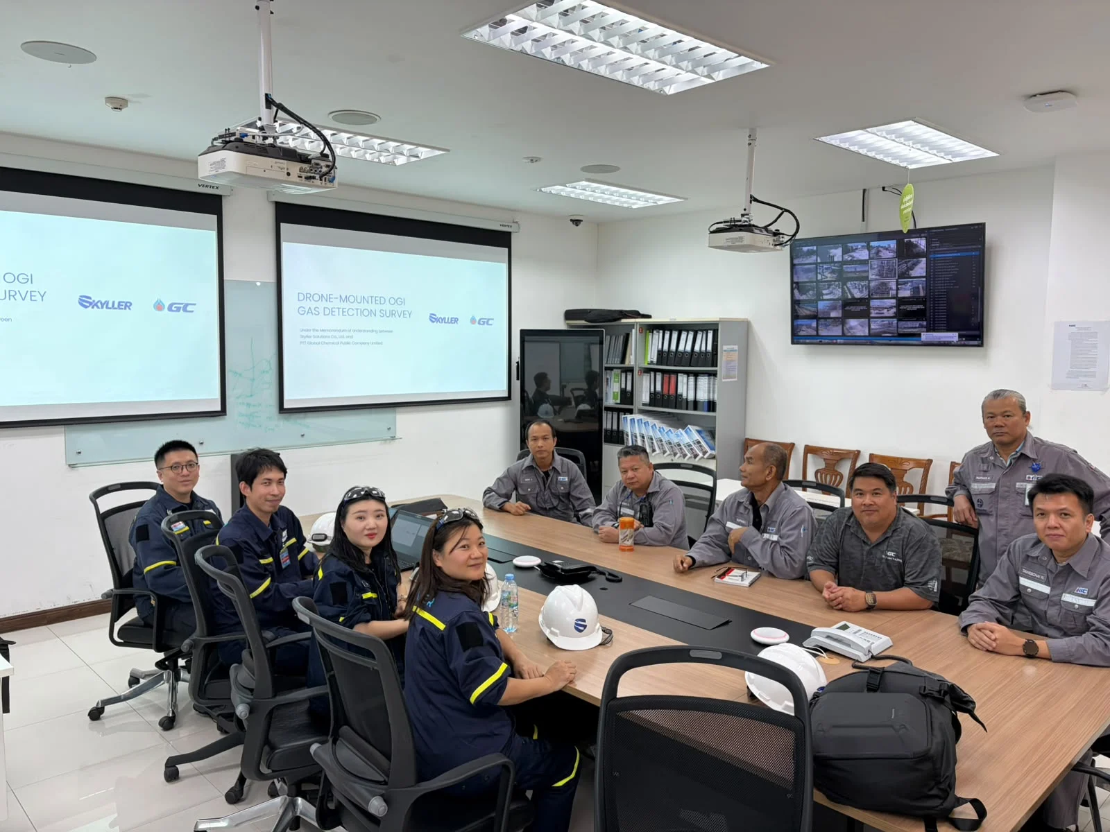
BLV conducted a GasVision-TD1 field test at a PTTGC floating-roof storage tank facility in Thailand. The demonstration produced clear gas plume imagery under the site conditions and received positive customer feedback.[5]
For each tank facility, equipment selection and inspection planning should account for the target gases, viewing access, operating conditions and instrument limitations.
Planning a storage tank gas inspection? Contact BLV to discuss your site requirements and a suitable field demonstration.
References
- U.S. EPA. AP-42, Chapter 7.1: Organic Liquid Storage Tanks. June 2026, Sections 7.1.1–7.1.3.
- U.S. EPA. Storage Tanks — Natural Gas STAR Program.
- Former Shanghai Environmental Protection Bureau. General Calculation Methods for VOC Emissions from Industrial Enterprises in Shanghai (Trial). 2017, Appendices E and F. Chinese-language technical reference.
Disclaimer: This guide provides general technical information. It does not cover every tank design or operating condition, or replace site procedures, instrument instructions or applicable requirements. Equipment faults and compliance status require appropriate site assessment by qualified personnel.